Operation of Laser-Driven Light Sources below 300 nm: Ozone Mitigation
Authors: H. Zhu and P. Blackborow
![Download Technical Note [PDF]](https://no-cache.hubspot.com/cta/default/5512327/e9c975ec-554b-42d0-9bc1-e6c615fc2e5d.png)
Introduction
Deep ultraviolet sources, such as Energetiq’s LDLS™, can produce ozone which can adversely affect the performance of instruments and experiments connected to the LDLS. Ozone in the optical path of an instrument will absorb UV light by varying amounts, depending on the ozone concentration. This application note explains the ozone generation mechanism and appropriate ozone mitigation techniques that will ensure the best possible results.
Ultraviolet (UV) Ozone Generation
When air (or oxygen) is exposed to UV radiation below about 200nm wavelength, ozone will be generated. Ozone (O3) is the tri-atomic form of molecular oxygen (O2). It is a colorless (at low concentration, blue at high concentration), unstable gas, with a distinctive sharp odor. Ozone is considered a pollutant for human health and it irritates the throat and eyes. Good ventilation is important when ozone is produced in a working environment. Ozone is a powerful oxidizer and will oxidize and degrade organic materials with which it comes into contact.
Ozone is produced when air is exposed to deep UV radiation through dissociation of oxygen molecules. When an oxygen molecule absorbs UV radiation, it breaks apart into two oxygen atoms (Eq. 1). These oxygen atoms combine with oxygen molecules to form ozone (Eq. 2).
O2 (g) + hν (UV, <200nm) = 2 O (1)
O + O2 (g) = O3 (g) (2)
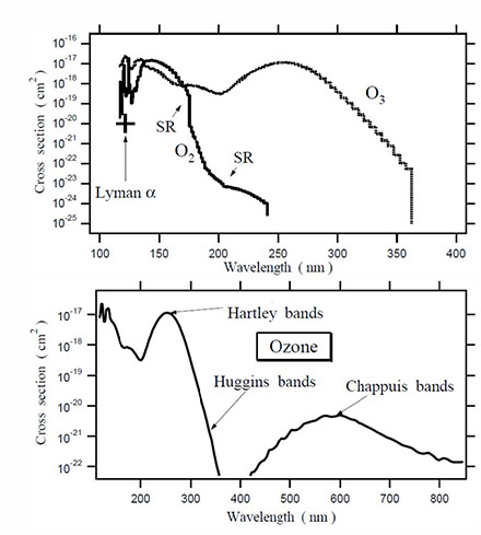
Ozone molecules in air can also absorb ultraviolet radiation, mainly at wavelengths between 220 nm and 280 nm, causing ozone molecules to decompose into oxygen molecules and oxygen atoms. (Eq. 3). Those oxygen atoms may again repeat the reaction shown in Eq. 2, or they may react with an ozone molecule to form two oxygen molecules as shown in Eq. 4.
O3 (g) + hν (UV, 220nm to 280nm) = O + O2 (g) (3)
O3 (g) + O = 2 O2 (g) (4)
This dynamic process can produce a situation where time-varying concentrations of ozone and oxygen are present along the UV beam path. Since both ozone and oxygen absorb deep UV light at various wavelengths, time-varying reduction in the UV is to be expected.
Irradiance
Irradiance is the radiometry term for the power per unit area of electromagnetic radiation incident on a surface. The SI unit for irradiance is watts per square meter [W/m2], or milliwatts per square millimeter [mW/mm2]. (Irradiance is sometimes called intensity, but this usage leads to confusion with another standard, but infrequently used, radiometry unit —Radiant Intensity — which is measured in watts per steradian.)
If a point radiation source emits radiation uniformly in all directions and there is no absorption, then the irradiance drops off in proportion to the distance squared from the source, since the total power is constant and it is spread over an area that increases with the distance squared from the radiation source. To compare the irradiance of different sources, one must take into account the distance from the source. A 50cm distance is often used for such measurements.
Irradiance is a useful measure for applications where power must be delivered to large areas. For example, illuminating a classroom or a football field is primarily a question of delivering a certain number of watts per square meter. This can be achieved by using a single high power source. However, since irradiance does not depend on solid angle, multiple sources can be combined, illuminating the walls or the field from different angles.
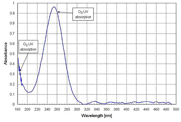
Figure 2. A spectral absorbance along a 50cm beam path, without nitrogen purge, using an EQ-99 LDLS
Ozone Mitigation in a UV Optical System
Energetiq’s Laser-Driven Light Sources produce high-brightness broadband radiation from 170 nm (the cut off of the high quality synthetic fused silica bulb) through visible and into the near infrared. Consequently, LDLS systems will generate ozone when oxygen in air is in the beam path, both inside and outside the lamp housing. In most LDLS applications, high-purity nitrogen purging of both the lamp housing and along the entire beam path is strongly recommended. Purging the lamp house and the beam path with high-purity nitrogen has a secondary benefit. Hydrocarbons present in air can also be photodissociated by deep UV light. These photodissociated hydrocarbon fragments can deposit on surfaces in the beam path as amorphous carbon-based thin-films which reduce optical transmission and reflection of those surfaces.
A nitrogen purge port is located on all LDLS lamp houses. It is recommended that high-purity (Grade 4.8) nitrogen is connected to this port to mitigate ozone production within the lamp house. For the optical beam path beyond the window of the LDLS, care should be taken in the instrument design or optical bench layout to allow for purging with nitrogen. The beam path should be made with purgeable optical tubes or enclosed in a box fitted with a nitrogen purge port. Keeping the volume low for the enclosure and ensuring close fitting seals and joint will minimize the flow rate of nitrogen needed to eliminate ozone production. In cases where a tightly fitting enclosure is not practical, the beam path may be aggressively ventilated with an exhaust system. By aggressively exhausting the area around the beam path, the concentration of ozone will be reduced, and the absorption in the 250 nm region will be reduced.
LDLS Applications Above 200nm
In LDLS applications where UV radiation below 200nm is not needed, special filters and window materials can be installed to replace the fused silica window on the lamp housing. Those window materials will practically eliminate the need to purge the beam path outside the lamp housing, since the major part of ozone generation is by UV radiation under 200 nm.
Energetiq recommends that the lamp house still be nitrogen purged to prevent ozone buildup inside the lamp housing. Ozone in the lamp house will absorb radiation between 220 nm and 280 nm.
Summary
- Ozone will be generated if air is exposed to radiation at < 200 nm.
- Ozone will reduce light output at 250 nm, +/- 30 nm.
- Exposure to ozone should be minimized for operator safety.
- The LDLS lamp house should be purged with nitrogen. The external beam path can be purged with nitrogen or actively exhausted to prevent ozone accumulation.
- For applications > 200 nm, ozone generation in the beam path can also be prevented by using a window on the LDLS that blocks radiation < 200 nm
References
[1] G. Kockarts, Annales Geophysicae (2002) 20: 585-598 (http://hal-insu.archives-ouvertes.fr/docs/00/31/ 69/92/PDF/angeo-20-585-2002.pdf)