Etendue and Optical Throughput Calculations
Authors: H. Zhu and P. Blackborow
![Download Technical Note [PDF]](https://no-cache.hubspot.com/cta/default/5512327/558361c3-f3f6-42b8-8ae4-726024545a56.png)
Introduction
This note is intended to help decide whether a Laser-Driven Light Source (LDLS™) is the appropriate source for an application. In this note we will consider only the optical performance and not other benefits of the LDLS, such as stability or ultra-long life. One of the main factors to consider is whether or not the étendue of the LDLS matches the étendue of the optical system. To have an optimized throughput in an optical system, the étendue of the light source, the collecting optics, and the étendue of the light receiving optics, optical fibers or monochromators, need to be closely matched. (In this Application Note, a monochromator can also mean a spectrometer or a spectrograph.)
In addition to the term “étendue,” other terms often used are “f-number” (F/#) and “numerical aperture” (NA). Etendue and its relationship to F/# and NA of an optical system will be discussed, in addition to discussions on how to use étendue and throughput calculations to select appropriate LDLS applications. For simplicity, diffraction and coherence effects are excluded in these discussions.
What is Etendue and Why Etendue Matching is Important for Effective Light Coupling
The term étendue comes from the French word for extent or spread. Other terms used for this property are Geometrical Extent (G), Optical Extent, and Optical Invariant. We will use G to represent étendue. For a LDLS source with relatively small cone of radiation (so paraxial optical approximation is valid), the étendue (G) of a light source is equal to the source emitting area (S) times the solid angle (Ω) from which the light is collected for a specific application, G ≈ SΩ [mm2-sr].
Etendue (G) describes the ability of a source to emit light or the ability of an optical system to accept light. For a monochromator, its étendue of accepting light is a function of the entrance slit area (S) times the solid angle (Ω) from which light is accepted. The étendue is a limiting factor for the throughput of the monochromator. A monochromator with smaller S and Ω will have smaller étendue.
A typical optical system includes a light source, light collecting and focusing optics, a monochromator, light delivery optics and a detector. Within every optical system there is one component that has the lowest étendue (Glim) which sets the limit of the entire system, and has the biggest impact to the performance of the entire optical system. Frequently, Glim is determined by the input slit dimensions and F/# of a monochromator, or the small diameter and numerical aperture (NA) of an optical fiber. Light coming from a larger étendue component will be partially accepted by the limiting component with the lowest étendue.
Due to its extremely small emitting area (~100μm in diameter), the LDLS radiation source from Energetiq has a very small étendue at a given light collection solid angle. The LDLS emits significantly higher radiation power per unit source area and per unit solid angle of emission. Such sources exhibit higher “radiance” (often called “brightness”) which is measured in units of mW/mm2-sr.
If an optical system has a much smaller étendue than that of a light source, a very small percentage of light coming out of the source will be coupled, no matter what optics are used to collect and focus the light.
In the opposite case, if an optical system has a much larger étendue than that of a source, nearly 100% of light coming out of the source can be coupled into the optical system, but the optical system will be unnecessarily large if the amount of light from the source is sufficient for the application.
The optimum case is where the étendue of the source closely matches the étendue of the optical system.
F-Number (F/#) and Numerical Aperture (NA)
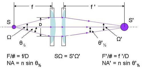
In coupling a light source to an optical system, be it an optical fiber or a monochromator, the best coupling efficiency is obtained by making the image (S’) of the light source (S) equal to that of the optical fiber diameter, or to the width of the monochromator, as well as making the solid angle (Ω’) of the focused light cone equal to the acceptance solid angle of the fiber or the monochromator. There are two parameters often used to describe the light collecting properties of optical fibers, monochromators and other optical components, one is numerical aperture (NA) and the other is f-number (F/#).
As shown in Figure 1, the light gathering power of an optical element is characterized by Numerical Aperture (NA), and it is expressed by:
NA = n sin θ½ (1)
where n is the refractive index (n = 1 in air), θ is the half acceptance angle of the cone of radiation.
F-number is defined by:
F/# = f/D (2)
F/# = 1/(2 tan θ½) (3)
For comparison purposes, deuterium (D2) lamps and a xenon (Xe) arc lamp are also calculated.
- D2 lamp with 500μm diameter plasma with 0.22NA collection, the étendue is 3.0E-02 [mm2-sr]
- D2 lamp with 1.0mm diameter plasma with 0.22NA collection, the étendue is 1.2E-01 [mm2-sr]
- 75W Xe short arc lamp, bright emitting area (cathode spot): 0.3 x 0.5 millimeters in dimension, 0.44NA collection, the étendue is 9.1E-2 [mm2-sr].
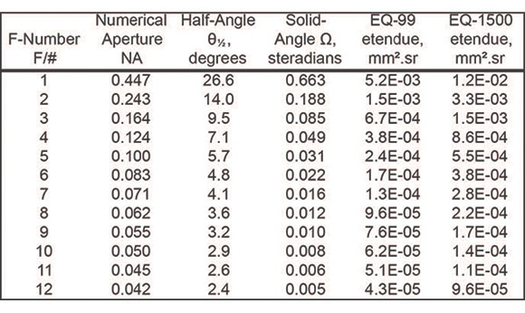
(Using the chart above, an EQ-99 collected with the same 0.44NA would have an étendue of ~4.9E-03 [mm2-sr])
The étendues of EQ-99 and EQ-1500 are one order or more lower, at the same NA conditions, than that of D2 lamps and 75W Xe lamps.
Sample Calculations of Etendue of Monochromator Slits and Optical Fibers
To assess the match between the source and the application, it is necessary to understand the étendue of the optics that will receive the light. The input étendue of an optical fiber is the product of the fiber NA (converted to solid angle (Ω) as in Table 1) and the fiber area in mm2. The input étendue of the monochromator slits is the product of the slit area in mm2 and the F/# of the monochromator, (converted to solid angle (Ω) as in Table 1). Some typical examples are listed below:
- Core diameter 200μm optical fiber with 0.22NA, the étendue is 4.78E-03 [mm2-sr], a good match to the LDLS
- Core diameter 500μm optical fiber with 0.22NA, the étendue is 2.99E-02 [mm2-sr], LDLS sources can be used.
- Core diameter 3mm optical fiber with 0.22NA, the étendue is 1.07 [mm2-sr], étendue is large compared to LDLS, and an arc lamp may be a better solution.
- An F/4 monochromator with 500μm slit width and 500μm slit height, the étendue is 1.21E-02 [mm2-sr]. For applications with this level of étendue or even lower, LDLS sources have significant advantages over other conventional light sources.
- An F/4 monochromator with 1mm slit width and 12mm slit height, the étendue is 5.80E-01 [mm2-sr]. Under this condition a conventional arc lamp may be better matched to a monochromator than an LDLS.
Examples of Throughput (Radiant Flux) Calculation
To understand the amount of light that will be coupled through an optical system, the radiant flux can be calculated. Radiant flux (Φ) is the radiation power (energy/time, W, or mW) into, for example, a fiber end or an entrance slit of a monochromator. Spectral radiant flux (Φλ) is the radiation power per unit wavelength [mW/nm]. They can be calculated as the product of radiance (R), or spectral radiance (Rλ) with the limiting étendue (Glim):
Φ[mW] = R[mW/mm2.sr] x Glim[mm2.sr] (1)
or
Φλ[mW/nm] = Rλ[mW/mm2.sr.nm] x Glim[mm2.sr] (2)
or
Because the étendue, and spectral radiance must be conserved between object and image, assuming no other losses, the above terms are all we need to determine the theoretical throughput - spectral radiant flux.
When making the calculation above, the étendue value to be used is the smaller of the source étendue or the optical system étendue, i.e. the limiting étendue (Glim).
Spectral Radiance (Rλ) for the EQ-99 and EQ-1500 LDLS, for 75W Xenon and for 30W D2 lamps are shown in Figure 2.
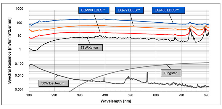
Figure 3: Spectral radiance of EQ-99X LDLS, EQ-77 LDLS, EQ-400, LDLS, 75W short-arc Xe Lamp, Tungsten Lamp and D2 lamp.
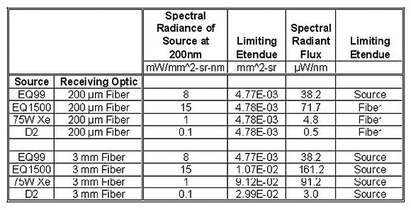
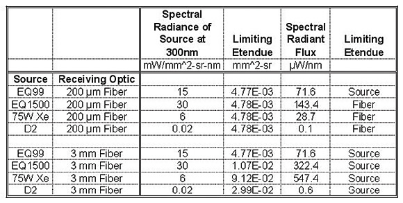
As an illustration, Tables 2 and 3 show the Spectral Radiant Flux into fibers of different diameters using 4 different light sources. We show the results at two wavelengths, 200nm and 300nm. The spectral radiance for the calculations is taken from Figure 2. As a result of this kind of analysis, it becomes clear which light source delivers the optimum spectral radiant flux (power/nm) for each application.